在使用GEF进行开发的时候,对于需要绘制的图形的节点,往往除了模型对象本身之外,还需要有一个相应的“图”对象来保存图中这个节点的位置,以及大小等图相关,但是与业务模型无关的一个对象。而在一开始希望显示一个初始模型文件的时候,再对应保存图信息的文件不存在的情况下,如何能够很好的显示这个图,是一个比较麻烦的问题,涉及到对布局算法的一些分析与实现。这片文章就是介绍,如何使用GEF内的DirectedGraph这个类以及其相应的布局算法类DirectedGraphLayout,来解决这个问题。
基本思想是:为GEF的EditPart模型生成一个DirectedGraph,然后使用DirectedGraphLayout来计算布局,最后将布局的结果通过GEF显示出来。
在参考了GEF的flow example之后,对其代码作了部分重构,写了这片文章,希望对遇到同样问题的同志能够有一定的帮助。
首先引入一个接口:
public interface GraphBuilder {
public void contributeNodesToGraph(DirectedGraph graph, Map map);
public void contributeEdgesToGraph(DirectedGraph graph, Map map);
public void applyGraphResults(DirectedGraph graph, Map map);
}
这个接口中定义了几个方法,其含义从其方法名中可以猜出:
contributeNodesToGraph:将当前对象作为节点(Node)添加到DirectedGraph中。
contributeEdgesToGraph:将当前对象所对应的连线作为边(Edge)添加到DirectedGraph中。
applyGraphResults:将图中生成的布局信息取出,对本对象进行重新布局。
接口中的graph参数就是保存的图的信息,map参数维持一个对象到节点/边的映射,使得每个对象能够方便的找到其对应的图中的节点或者边。这个接口的使用,在后面会有涉及。下面先看看显示图的容器是如何构建的。
图的容器定义为GraphDiagramEditPart,这个EditPart对应于要显示的有向图的容器。它实现了GraphBuider接口,这也是我们主要需要关注的接口:
public class GraphDiagramEditPart extends AbstractGraphicalEditPart implements
GraphBuilder.
contributeNodesToGraph方法将自身作为节点添加到图中,但是因为GraphDiagramEditPart对应的是容器,因此它不需要向图中添加信息,只是调用其子EditPart,将其添加到图中。
public void contributeNodesToGraph(DirectedGraph graph, Map map) {
for (int i = 0; i < getChildren().size(); i++) {
NodeEditPart activity = (NodeEditPart)getChildren().get(i);
activity.contributeNodesToGraph(graph, map);
}
}
contributeEdgesToGraph方法将这个EditPart的所有子EditPart取出,调用其contributeEdgesToGraph方法,通过这个方法,就可以将所有的边添加到图中了:
public void contributeEdgesToGraph(DirectedGraph graph, Map map) {
for (int i = 0; i < getChildren().size(); i++) {
NodeEditPart child = (NodeEditPart)children.get(i);
child.contributeEdgesToGraph(graph, map);
}
}
applyGraphResults方法将所有取出所有的子EditPart,并调用其applyGraphResults,使得图中所生成的布局信息能够被应用到显示上。
public void applyGraphResults(DirectedGraph graph, Map map) {
applyChildrenResults(graph, map);
}
protected void applyChildrenResults(DirectedGraph graph, Map map) {
for (int i = 0; i < getChildren().size(); i++) {
GraphBuilder part = (GraphBuilder) getChildren().get(i);
part.applyGraphResults(graph, map);
}
}
下面要介绍的是NodeEditPart,它作图中所有节点所对应的EditPart的抽象父类,也实现了GraphBuilder接口。每一个要做为节点添加到图中的EditPart,应该继承这个类。
public abstract class NodeEditPart extends AbstractGraphicalEditPart implements
GraphBuilder{
public void contributeNodesToGraph(DirectedGraph graph,
Map map) {
Node n = new Node(this);
n.outgoingOffset = 7;
n.incomingOffset = 7;
n.width = getFigure().getPreferredSize().width;
n.height = getFigure().getPreferredSize().height;
n.setPadding(new Insets(10,8,10,12));
map.put(this, n);
graph.nodes.add(n);
}
public void contributeEdgesToGraph(DirectedGraph graph, Map map) {
List outgoing = getSourceConnections();
for (int i = 0; i < outgoing.size(); i++) {
EdgeEditPart part = (EdgeEditPart)getSourceConnections().get(i);
part.contributeEdgesToGraph(graph, map);
}
}
public void applyGraphResults(DirectedGraph graph, Map map) {
Node n = (Node)map.get(this);
getFigure().setBounds(new Rectangle(n.x, n.y, n.width, n.height));
for (int i = 0; i < getSourceConnections().size(); i++) {
EdgeEditPart trans = (EdgeEditPart) getSourceConnections().get(i);
trans.applyGraphResults(graph, map);
}
}
}
再就是边所对应EditPart的抽象类EdgeEditPart。每一个要作为边添加到图中的EditPart,需要继承这个类。在上面NodeEditPart中对其所对应的Figure其实并没有什么要求,但是对EdgeEditPart所对应的Figure,要求其Figure必须由一个BendpointConnectionRouter,作为其ConnectionRouter:setConnectionRouter(new BendpointConnectionRouter())。这样图的边的路径信息才能够被显示出来。
public abstract class EdgeEditPart extends AbstractConnectionEditPart implements
GraphBuilder {
public void contributeEdgesToGraph(DirectedGraph graph, Map map) {
Node source = (Node)map.get(getSource());
Node target = (Node)map.get(getTarget());
Edge e = new Edge(this, source, target);
e.weight = 2;
graph.edges.add(e);
map.put(this, e);
}
public void applyGraphResults(DirectedGraph graph, Map map) {
Edge e = (Edge)map.get(this);
NodeList nodes = e.vNodes;
PolylineConnection conn = (PolylineConnection)getConnectionFigure();
conn.setTargetDecoration(new PolygonDecoration());
if (nodes != null) {
List bends = new ArrayList();
for (int i = 0; i < nodes.size(); i++) {
Node vn = nodes.getNode(i);
int x = vn.x;
int y = vn.y;
if (e.isFeedback) {
bends.add(new AbsoluteBendpoint(x, y + vn.height));
bends.add(new AbsoluteBendpoint(x, y));
} else {
bends.add(new AbsoluteBendpoint(x, y));
bends.add(new AbsoluteBendpoint(x, y + vn.height));
}
}
conn.setRoutingConstraint(bends);
} else {
conn.setRoutingConstraint(Collections.EMPTY_LIST);
}
}
}
最后的就是一个LayoutManager来初始化图的创建,以及对图的信息进行解释了,生成最终布局了。这个GraphLayoutManager作为GraphDiagramEditPart所对应的GraphDiagram的LayoutManager,来显示图的内容。
public class GraphLayoutManager extends AbstractLayout {
private GraphBuilder diagram;
GraphLayoutManager(GraphBuilder diagram) {
this.diagram = diagram;
}
protected Dimension calculatePreferredSize(IFigure container, int wHint,
int hHint) {
container.validate();
List children = container.getChildren();
Rectangle result = new Rectangle().setLocation(container
.getClientArea().getLocation());
for (int i = 0; i < children.size(); i++)
result.union(((IFigure) children.get(i)).getBounds());
result.resize(container.getInsets().getWidth(), container.getInsets()
.getHeight());
return result.getSize();
}
public void layout(IFigure container) {
DirectedGraph graph = new DirectedGraph();
Map partsToNodes = new HashMap();
diagram.contributeNodesToGraph(graph, partsToNodes);
diagram.contributeEdgesToGraph(graph, partsToNodes);
new DirectedGraphLayout().visit(graph);
diagram.applyGraphResults(graph, partsToNodes);
}
}
可以看到在layout方法中,首先生成了一个DirectedGraph,并调用了contributeNodesToGraph以及contributeEdgesToGraph方法,将节点和边的信息添加到这个生成的DirectedGraphGraph中,然后使用布局算法DirectedGraphLayout().visit(graph)来计算生成图的信息(这里使用了visitor模式)最后调用applyGraphResults将图的信息应用到图形的显示上。
至此,所有框架的工作做完了,如果要将模型作为一个有向图显示的话,只需要将模型的容器对象对应于GraphDiagramEditPart(在EditPartFactory中进行映射),为每一个需要表示为节点的对象,对应到一个继承于NodeEditPart的EditPart,为每一个需要表示为边的模型对象,对应到一个继承于EdgeEditPart的EditPart。这样,就能够将图的布局算法,应用到GEF框架中了。
这里写的比较简单,使用起来也会有一些具体的约束。例如在有向图中,是不能够有孤立的节点的。如果使用CompoundDirectedGraph,就不会有这样的问题,CompoundDirectedGraph可以包括子图,可以支持更为复杂的图形。在Flow Example中使用的就是CompoundDirectedGraph。在后面,我或许会将这个框架进行改写,以使其支持CompoundDirectedGraph来进行布局算法。下面的图是一个生成的例子,大家可以看一下效果:
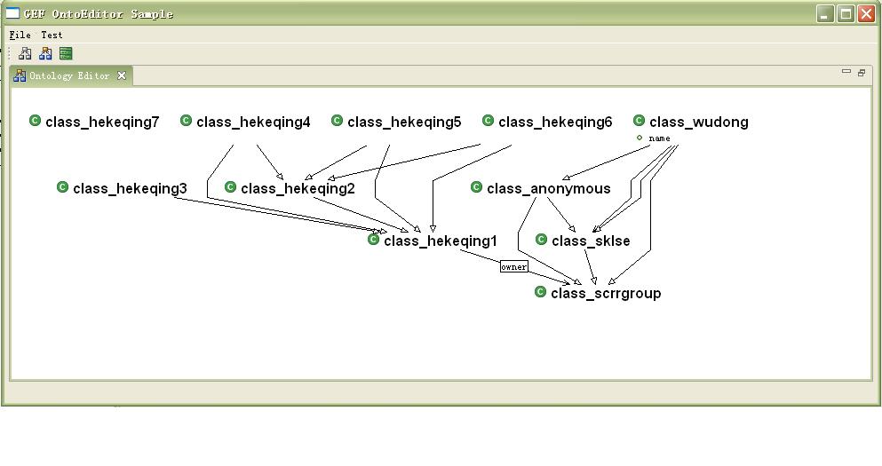
这是从OWL文件中读取内容之后生成的一个图的表示。可以看到,OWL的节点通过自动图的自动布局之后,已经有了较好的视觉效果。如果没有这样的布局的话,因为单纯的OWL文件中并不会包含节点的图的信息,图显示出来会变得非常的乱,所有的节点都会堆在一起。
原文地址:http://www.blogjava.net/eclipshine/archive/2005/07/22/8195.aspx